The Why
In late 2021, I began searching for an interesting topic for my final degree project. I wanted to work on something meaningful but accessible to the strict time constraints and knowledge I had. I’d always been an ambitious student, and I wanted to challenge myself.
My friend Shexing joined a student project starting in September 2021. He was selected to be part of BCN eMotorsport. This team was building an electric driverless racing car for Formula Student competitions held across Europe in countries like Austria, Germany, and Spain.
Shexing shared his experiences with BCN eMotorsport and convinced me to meet the team. Although I’d never been particularly interested in cars, I agreed to visit their headquarters. There, I talked with Jesús and Mikel, who showed me the team’s startup-like spirit and introduced me to the most ambitious challenge they were facing: designing a custom motor drive for the car.
In Februry 2022, I joined the project alonside Albert, a new team member. We divided the project on two main parts:
- Hardware: Choosing components and designing the power board.
- Control: Designing and implementing the control algorithm on an FPGA.
Since I had experience with digital design and programming, I took on the control part, while Albert managed the hardware. Soon enough, the team nicknamed us the “Inverter Bros,” and we made steady progress together.
The Project
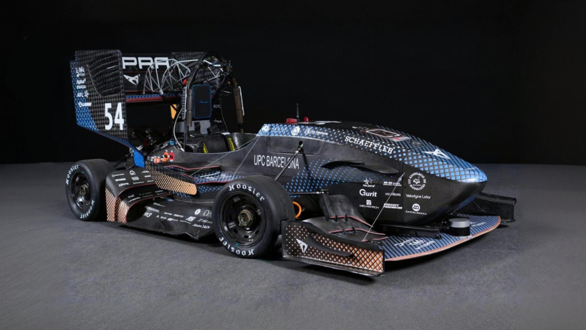
The CAT14x, the BCN eMotorsport single-seater of 2022.
The custom motor controller project aimed to replace the existing commercial inverters, a pair of Lenze Mobile DSU 60/60, with a more tailored and efficient solution, improving our four-wheel-drive Formula Student car’s performance on the track.
The Lenze inverters are bulky, designed for much larger vehicles, and their internal workings are not customizable to the team’s needs. The new inverter was designed to take advantage of silicon carbide (SiC) MOSFET technology, allowing for a higher switching frequency compared to the IGBTs used in the current inverters. Additionally, the protective housing of the new inverter was anticipated to significantly reduce the weight of this component.
My Contribution
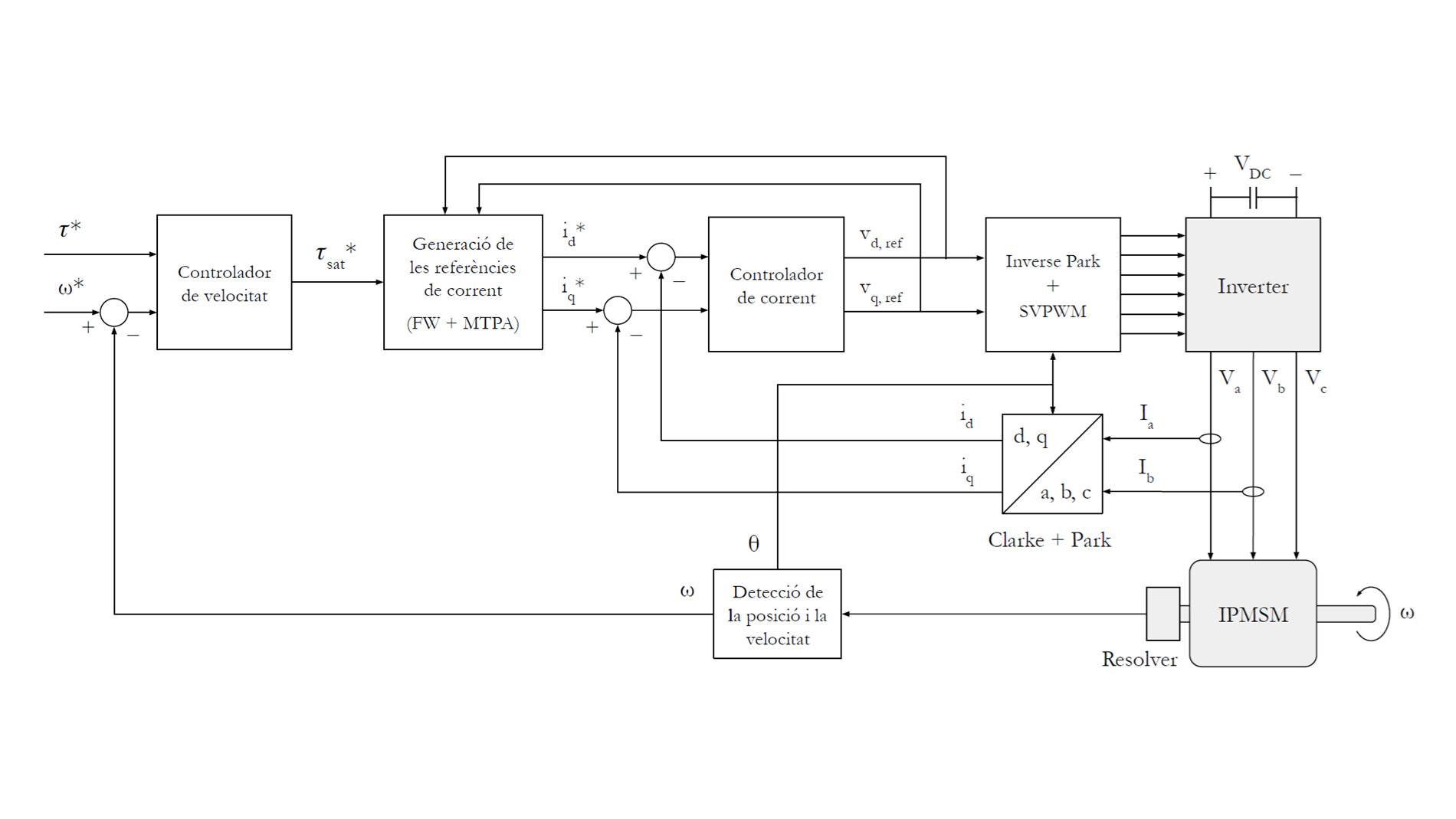
My role in the project involved implementing a field-oriented control (FOC) algorithm on a field-programmable gate array (FPGA) board. The algorithm was tailored for the permanent magnet synchronous motor (IPMSM) used in BCN eMotorsport’s single-seater.
The main objectives of the thesis project were:
- Hardware Selection: Choosing an FPGA board and a resolver or encoder.
- Control Algorithm Analysis: Refining the initial team-developed algorithm.
- FPGA Implementation: Implementing the control algorithm on a System on Module with FPGA.
- Microcontroller Software Design: Developing software on the microcontroller to receive commands over CAN bus.
- Control Algorithm Validation: Verifying the performance of the implemented control algorithm.
If you are curious, you can download the full thesis here in catalan.
Theoretical Framework
Schematic of an ideal inverter.
The IPMSM can be modeled as an inductance and resistance in series for each phase. There are two types of connections in a three-phase motor: star and delta. In this instance, the connection was a star connection: the three branches of the motor are joined at a midpoint called the neutral point, symbolised by an ’n'.
The chosen inverter topology was the two-level inverter (TLI). This decision was based on factors including the team’s experience, battery configuration, loss analysis, and considerations of size, weight, and cost.
To control the motor, a field-oriented control (FOC) algorithm was selected. This algorithm is widely used in electric vehicle applications due to its ability to provide high torque at low speeds and high efficiency at high speeds. Two advanced techniques were used to enhance the FOC algorithm’s performance:
- Maximum Torque per Ampere (MTPA), which provides the motor with optimal instructions at every moment to maximize torque while minimizing energy consumption.
- Field weakening (FW), a strategy that cleverly adjusts the magnetic field to allow the motor to spin faster.
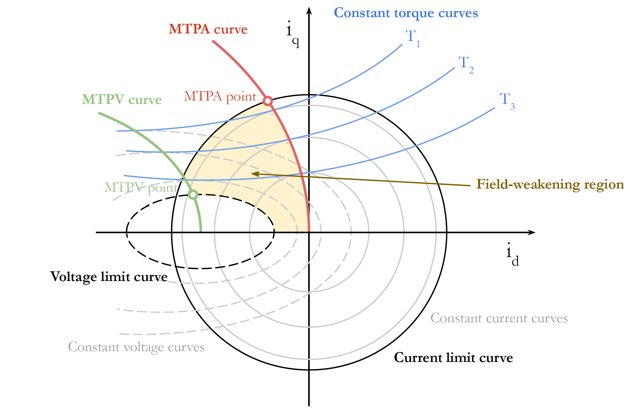
The operating regions of the motor controller, in the d-q frame.
FOC uses a series of clever transformations:
Clarke Transform: This takes the three-phase currents coming from the motor (a-b-c frame) and translates them into a simpler coordinate system (α-β frame). It’s similar to taking a 3D object and flattening it onto a 2D surface – you’re simplifying the representation without losing essential information.
Park Transform: This takes the simplified currents and aligns the reference frame with the rotation magnetic field of the motor (from the α-β frame to a rotating d-q frame). It’s like spining your watch at the same time as the second hand, creating the illusion that it’s not moving at all. With this, we can decouple the control of the magnetic flux and torque, making it easier to manage the motor’s behavior.
In addition, FOC requires a modulation technique to convert the voltage vector output from the controller into a voltage measured in the inverter phases. Space Vector Pulse Width Modulation (SVPWM) was used for this purpose. This technique is more efficient than traditional PWM methods, as it allows for smoother transitions between voltage levels, reducing harmonic distortion and improving motor performance.
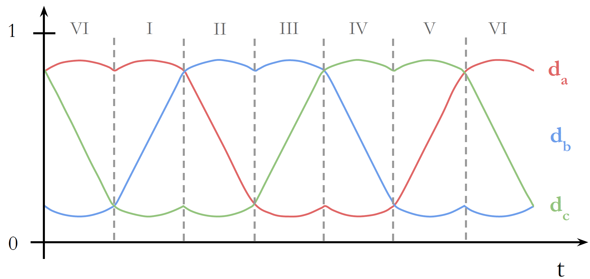
SVPWM generated duty cycles, with its characteristic M shape.
Design Considerations and Implementation
Why an FPGA?
For the implementation, it was decided to use an FGPA instead of relying only on a microprocessor. FPGAs are like digital Legos, allowing us to build custom circuits tailored to our exact needs. This is why it is called programmable logic, since it creates logic circuits with a program.
In the context of motor control, FPGAs offer several key advantages:
Parallel processing: FPGAs can perform multiple operations simultaneously. This is crucial for motor control, where we need to process information and adjust signals in real-time to maintain optimal performance.
Deterministic timing: FPGAs ensure that signals are delivered at exactly the right moment. This is especially important when working with SiC MOSFETs, which can switch on and off incredibly fast, requiring precise control to maximize efficiency and prevent damage.
The chosen SoC was the Zynq-7010 from Xilinx, which combines an FPGA with a powerful microprocessor, giving us the best of both worlds. This SoC was firstly housed on a Diligent Cora Z7-10 development board, which was later replaced with a MYIR Z-Turn board to provide more logic resources, GPIOs, and better documentation.

Testing with the Diligent Cora Z7-10
Toolset
The project was developed using a combination of tools:
- Vitis Model Composer, a Matlab/Simulink® extension, was used to implement the programmable logic. This low-code environment provides a blockset for describing and implementing programmable logic, which offered faster development and testing compared to writing code in a hardware description language like VHDL.
- Vivado was used for the synthesis, implementation, and debugging of the FPGA design.
- PetaLinux was utilized as an operating system for managing the microprocessor.
- C++ was the language to develop the state machine, user interface, and CAN communication with other vehicle systems.
Resource Optimization
An important part of the project implementation was the decision-making process used to optimize the control system for the inverter, including the reduction of resource usage selecting the right data types (fixed-point arithmetic), pipelining for lower dynamic power consumption, and dead time adjustments in the gate drivers to prevent shoot-through issues in the inverter.
Software Integration
On the software side, a state machine was implemented to control the motor start and stop, and a user interface was created to monitor the motor’s status and set the speed and torque setpoints. Custom C++ classes represented registers and sensors, allowing to create a modular layer of abstraction of the communication between the FPGA and microprocessor.
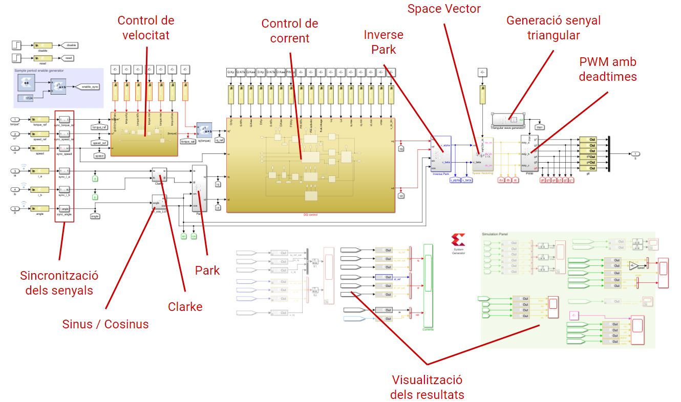
Final implementation of the control algorithm in Vitis Model Composer.
Conclusions
Innovative projects are rarely smooth, and this one was no exception. I encountered challenges debugging the complex control algorithm in the Vivado Model Composer platform. The hard work finally paid off, and the full implementation of the FOC algorithm was successfully simulated in the FPGA.
More than just a technical achievement, this project taught me valuable lessons about how to work on large and complex developments. I knew that this was an ambitious projects, but I was eager to complete it. However, I could not complete all the objetives I had set at the beginning since I was not aware of the complexity of the project. I learned that it is important to study the problem in depth before starting to work on it, and then set realistic goals and to be flexible when things don’t go as planned.
A Look Back
Reflecting on my time at BCN eMotorsport, I look back this project with pride. We followed the project for another half a year, working on the things we planned on the Future Work section. As a Team Leader the following year, I decided to abandon the project since it not longer fitter the team’s strategy. Altough it would have been a great improvement for the team’s future cars, the project was too ambitious and it was not the best way to spend the scarce resources in terms of time and personnel. Through great communication within the team, we opened the eyes and realized that many others projects could have had the same impact in the competitions with less effort.
This second year at BCN eMotorsport taught me a most important, critical lesson: a good engineer must question the project requirements and objectives to avoid wasting months of work and other resources.
 See on GitHub